
Easiest of agitating applications and normally axial turbine or hydrofoil impellers are preferred. Jet mixing by recirculation with an ordinary pump is equally good at lower cost
In dissolving, we want provision of high flow rate and low shear past the solid surface. Unless the solid is polymeric or sticky or viscous in nature, it is an easy operation. Data solicited are solid percentage, physical characteristics with interim changes, temp, solubility and permissible dissolving time.
Dispersion refers to mixing of non-miscible liquids or of solids in liquids, into somewhat homogeneous mass whose stability is measured by its life before reasonable separation occurs. Power input varies greatly depending on purpose and impellers generally used are pitched blade turbine, or saw tooth cutter. This is most critical of mixing problems and unless properly understood, the design is liable to fail.
Used to speed up heat transfer by forced convection. Apparently simple but for critical applications, following data helps.
Imparting a high power to break the molecular chains and to form the oil-water emulsion with a non-ionic surfactant. Other applications are mainly in paints & lubricants sector. Some emulsion may be steady for years and some break within minutes. Static mixers are preferred than agitators for high instantaneous power resulting better emulsion but washing pump & pipeline is problematic.
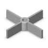
It is simple physical (like mixing) operation but power consumption varies greatly on purpose e.g. a> complete motion of solids, b> complete suspension of solids, c> complete uniformity. Power req. is in ratio of 1: 2: 5 for said operations.
It can be considered as combination of blending, dissolving, heat transfer, extraction, gas dispersion, and solid suspension etc. Usually an easy task from agitator designer’s point but to be sure, pilot plant study is always recommended. A haphazard selection is vulnerable and over design (like peripheral impeller tip speed) has various detrimental effects on the final product.
This is normally a continuous counter- current (fluidized bed) process like solid suspension involving water to be well mixed up with other ingredients and the ingredients separates out by gravity separation. Usually of interest for mining people.
Gas is impregnated from bottom as small bubbles and intimately distributed throughout the liquid usually resulting a chemical reaction. Generally curved vane impeller or multiple turbines are preferred with high speed. Fully baffled tanks should be tall and narrow in construction. Pressurized chamber accelerates the process. A better way is by static mixer employing a liquid pump and a pressurized semi- permeable solid wall to impregnate gas under pressure.
It is opposite of dissolving and is accomplished by cooling a saturated solution or by heating to drive out the solvent. The heat transfer requires a good flow. Satisfactory handling of crystals is of prime importance. Pilot plant data are desired. Generally crystals deposit at the bottom but if process deserves to be uniformly suspended, much study on the crystal structure & sensitivity is to be made for speed selection. Fluid-foil or aerofoil impellers with high flow and low shear are suggested.
As like fan (for air handling) or hydel power turbines, much research has been conducted towards agitator impeller design and it is a very wide subject with much more further scope to research and improve. Impeller is designed mainly keeping in mind the purpose or application and sometimes custom built.
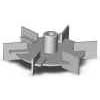
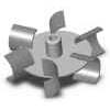
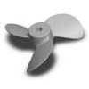
Looks like a table fan blade. Suitable for high flow and low shear e.g. blending, dissolving, heat transfer, etc. Unsuitable for solid suspension, dispersion, extraction, gas dispersion, etc. flow efficiency- 50-60%. Getting outdated but manufacturers with their old proven designs are still sticking to that.
Looks like a table fan blade. Suitable for high flow and low shear e.g. blending, dissolving, heat transfer, etc. Unsuitable for solid suspension, dispersion, extraction, gas dispersion, etc. flow efficiency- 50-60%. Getting outdated but manufacturers with their old proven designs are still sticking to that.
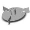
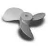
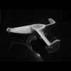
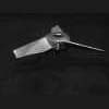
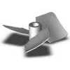
Hydrofoil is supposed to be a foil in water and looks like pitched blade turbine with an angled cut on the lower periphery. Its flow efficiency is better than marine propeller, replacing the later in most applications and is most desired for mixing purposes but unsuitable for high shear application.
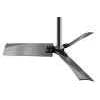
aerofoil is having a classic stand fan blade type look and its properties are almost like hydrofoil impellers. Of interest for mining people for mineral washing and beneficiation for energy efficiency.
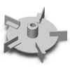
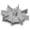
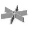
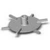
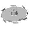
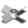
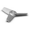
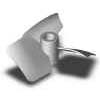
Curved Vane impeller looks like straight Pelton wheel designed to hold moving particles for some time e.g. for air absorption.
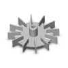
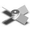
Old outdated design supposed to bring highest shearing action and usually specified for oil-water emulsion.
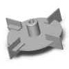
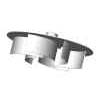
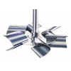
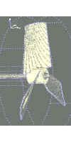
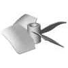
Saw Tooth Cutter is reasonably good for handling medium to high viscous liquids. It is most economic for emulsification. Bad design for blending simple solutions as well as handling semi solids (grease, honey etc.). Suggested for oil-water emulsion, lubricants, paints, etc.
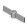
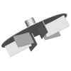
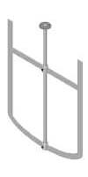
Anchor (with its namely look) is used for heat transfer from bottom or scraping viscous liquids.
WHERE
Power calculation in viscous fluid is cumbersome and then also is unreliable. We shamefully take motor margins as 50% minimum. For basics, BHP varies with 1st. power of rpm and 3rd. power of impeller diameter for viscous impellers. In fact for thumb rule at low speed, wattage equals the weight of total mass in grams transferred except in thixotropic conditions.
For both turbulent and viscous motion flow rate is determined by
WHERE
The agitator price is somewhat very little in comparison to what a process would gain and deserves from a reasonably good design.
Pilot plants do come and go but the commercial plant determines the profit percentage. It is always suggestable to go for much in-depth of pilot plant studies before arriving at the big risk time.
Furthermore, in case of any doubt, checks and cross checks from different agencies are likely to be obtained and it is available at reasonable cost. Designer should have adequate experience in the proper application you are trying to achieve.
In case you have any quarries/ suggestions, I would be glad to share our knowledge.
Radial Impellers |
|||
|---|---|---|---|
 |
 |
 |
|
| RT3 | RT4 | RT5 | |
| Rushton Turbine with 3 blades | Rushton Turbine with 4 blades | Rushton Turbine with 5 blades | |
| Np=3.3, Nq=0.62* D/T=0.33, wB/T=1/12 | Np=4.3, Nq=0.68* D/T=0.33, wB/T=1/12 | Np=5.4, Nq=0.73* D/T=0.33, wB/T=1/12 | |
| Np=3.4, Nq=0.62* D/T=0.33, wB/T=0.1 | Np=4.4, Nq=0.68* D/T=0.33, wB/T=0.1 | Np=5.4, Nq=0.73* D/T=0.33, wB/T=0.1 | |
 |
 |
 |
|
| RT6 | RT8 | RT12 | |
| Chemineer D-6, Lightnin R100, Hayward Gordon RD | Rushton Turbine with 8 blades | Rushton Turbine with 12 blades | |
| Rushton Turbine with 6 blades, Np=5.2, Nq=0.72 | Np=7.8, Nq=0.82* D/T=0.33, wB/T=1/12 | Np=9.9, Nq=0.89* D/T=0.33, wB/T=1/12 | |
| Np=6.0, D/T=0.33, wB/T=1/12 | Np=7.8, Nq=0.82* D/T=0.33, wB/T=0.1 | Np=10.0, Nq=0.90* D/T=0.33, wB/T=0.1 | |
| Np=6.0, D/T=0.33, wB/T=0.1 | |||
 |
 |
 |
|
| RP2 | RP4 | RP6 | |
| Paddle with 2 blades | Lightnin R200 | Paddle with 6 blades | |
| No disk (disc) | Paddle with 4 blades | No disk (disc) | |
| No disk (disc) Np=3.4, Nq=0.62* | |||
  |
  |
 |
|
| Holmes & Narver pumper mixer | Curved bladed pumper | RS6 | |
| Lightnin R300 | Lightnin R320, Philadelphia Mixers CBT-6 | Chemineer CD-6, Lightnin R130 | |
| Np, Nq, and Nh-values | Pumper impeller used for solvent extraction mixer settlers | Philadelphia Mixers Smith Turbine, Hayward Gordon RDC | |
| CFD study | 6-curved blades on one side of disk | Np=3.2, Nq=0.61* | |
| CFD study | |||
 |
 |
 |
|
| Chemineer BT-6 | Bar turbine | Sawtooth, Disperser | |
| Np=2.3, Nq=0.55* | Lightnin R510 | Lightnin R500 | |
| Np=0.65, Nq=0.36* | Np=0.45, Nq=0.32* | ||
| Experimentally derived Np and Nq values coming soon! | |||
Axial Impellers |
||
|---|---|---|
  |
 |
 |
| PR-D and PR-U | 4PBT-D and 4PBT-U | 6PBT-D |
| Chemineer AP-3, Lightnin A100 and A110 | Chemineer P-4, Lightnin A200 | Pitched bladed turbine - Down-pumping with 6 blades |
| Propeller - Down-pumping and Up-pumping | Pitched blade turbine - Down-pumping and Up-pumping with 4 blades | |
| Np=0.32 for 1.0 pitch, D/T=0.35, wB/T=0.1 | Np=1.27, Nq=0.79 | |
| Np=0.36 for 1.0 pitch, D/T=0.22, wB/T=0.1 | ||
| Np=0.62 for 1.5 pitch, D/T=0.22, wB/T=0.1 | ||
| Np=1.00 for 2.0 pitch, D/T=0.31, wB/T=0.1 | ||
| Np=1.35 for 2.5 pitch, D/T=0.22, wB/T=0.1 | ||
| Note: Subtract 0.01 from Np for wB/T=1/12 | ||
 |
  |
 |
| Lightnin A6000 (down-pumper) | Lightnin A310 or A510 (down-pumper) | Chemineer HE-3 (down-pumper) |
| Advanced fiber reinforced composite, utilizing highly corrosion resistant plastic matrix, with proplets | Np=0.30, Nq=0.56 | Np=0.20, Nq=0.46 for D/T=0.5 |
| Lightnin A6100 (down-pumper) | Np=0.22, Nq=0.47 for D/T=0.4 | |
| Like the A6000 without proplets | Np=0.26, Nq=0.49 for D/T=0.3 | |
| Np=0.23, Nq=0.59 | Np=0.30, Nq=0.50 for D/T=0.2 | |
 |
 |
 |
| Lightnin A312 | Lightnin A320 (down-pumper) | Lightnin A340 (up-pumper) |
| impeller mainly for side entry applications | Np=0.64, Nq=0.64 | Np=0.64, Nq=0.64 |
 |
|
  |
| Lightnin A315 (down-pumper) | Lightnin A345 (up-pumper) | Specialty Impellers |
| Np=0.75, Nq=0.73 | Np=0.75, Nq=0.73 | |